 Catalizadores de la serie Minslite para eliminación de ozono/CO/VOC
La pérdida de actividad del catalizador es uno de los desafíos operativos más comunes en las unidades catalíticas industriales.. Entre los diversos factores de desactivación., Cobertura física y ocupación química de sitios activos por vapor de agua y polvo. representan el más directo, frecuente, y causa raíz fácilmente diagnosticada erróneamente de fallas a corto plazo, particularmente en lugares con mucho polvo, Procesos de alta humedad, como la desnitrificación SCR en centrales eléctricas alimentadas con carbón., desnitrificación en horno de cemento, y combustión catalítica de COV.
Tomando como ejemplo los catalizadores de desnitrificación SCR, El costo de instalación inicial generalmente representa entre el 30% y el 50% de la inversión total en el sistema de desnitrificación.. La desactivación prematura debido a la cobertura del sitio activo no solo genera altos costos de reemplazo sino que también puede llevar a exceder las emisiones de NOx.. A diferencia de los mecanismos de desactivación permanente como el envenenamiento químico y la sinterización térmica., la pérdida de actividad causada por la cobertura de vapor de agua y polvo es en gran medida reversible o recuperable mediante medidas técnicas. Identificar con precisión el tipo de falla, comprender los mecanismos subyacentes, e implementar contramedidas específicas son clave para extender la vida útil del catalizador y reducir los costos de operación y mantenimiento..
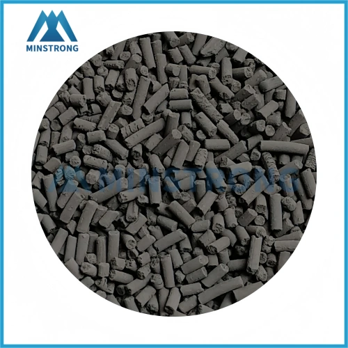
catalizador de monóxido de carbono
1. Mecanismos de acción del vapor de agua: De la adsorción reversible al envenenamiento sinérgico
El impacto del vapor de agua en los sitios activos abarca un espectro continuo desde la adsorción física hasta la modificación química..
1.1 Adsorción competitiva (Reversible)
Las moléculas de agua compiten con las moléculas reactivas por los sitios activos finitos.. Los estudios demuestran que la inhibición de la reacción SCR por el vapor de agua depende de la concentración: cuando el contenido de vapor de agua es inferior 8 % vol., domina la adsorción competitiva. La temperatura es el factor de control clave, a bajas temperaturas., las moléculas de agua se adsorben molecularmente, ocupando sitios ácidos de Bronsted y sitios ácidos de Lewis; a medida que aumenta la temperatura, El tiempo de residencia superficial del agua se acorta., y el efecto competitivo se debilita significativamente. Los cálculos de DFT indican que el H₂O interactúa fuertemente con los átomos de titanio en la superficie V₂O₅/TiO₂, y cuando la cobertura de agua en los sitios de adsorción excede 15%, la tasa de adsorción de NH₃ en sitios VOx se ve notablemente obstaculizada.
1.2 Hidroxilación de superficies y transformación de fase activa (Irreversible)
Bajo exposición prolongada al vapor de agua, La interacción evoluciona desde la adsorción física hasta la transformación química.. Para catalizadores basados en Pd, La pérdida de actividad en la etapa inicial se debe principalmente a la adsorción competitiva., pero después de un funcionamiento prolongado, PdO se convierte gradualmente en Pd(OH)₂ especies, causando daños irreversibles. Diferentes sistemas exhiben diferentes sensibilidades.: sobre catalizadores MnCeTi, El H₂O se disocia más fácilmente para formar grupos hidroxilo., que suprimen más fuertemente la adsorción de NH₃; Los catalizadores CuCeTi muestran una resistencia al agua relativamente mejor a bajas temperaturas.
1.3 Sinergia ternaria de vapor de agua, SO₂ y metales alcalinos (Más destructivo)
En condiciones de SCR de baja temperatura, SO₂ se oxida a SO₃, que luego reacciona con vapor de agua para formar H₂SO₄, y posteriormente con NH₃ para depositar sulfato de amonio o bisulfato de amonio sobre la superficie del catalizador.. Un camino más insidioso es el de “disolución-migración-redeposición”: cuando la temperatura de los gases de combustión cae por debajo del punto de rocío, Las películas de agua condensada lixivian metales alcalinos solubles. (K⁺, Na⁺) y metales alcalinotérreos procedentes de cenizas volantes, que migran hacia los poros internos a través de la condensación capilar y, después del secado, depositarse como óxidos o sulfatos. Este proceso combina bloqueo físico y envenenamiento químico., y generalmente es irreversible.
2. Deposición de polvo y sinergia agua-polvo
El impacto del polvo se manifiesta como ocupación espacial y obstrucción de la transferencia de masa a nivel de partículas..
2.1 Deposición superficial
Las partículas de cenizas volantes se depositan en la superficie del catalizador mediante impactación inercial., interceptación, difusión, y adhesión electrostática, Formar una capa de cobertura que constituye una barrera física difícil de superar para las moléculas reactivas.. La distribución desigual del flujo de gases de combustión es un factor clave: las zonas de baja velocidad promueven la deposición de cenizas y el bloqueo de canales, mientras que las zonas de alta velocidad causan erosión y tiempo de contacto insuficiente. Según GB/T21509‑2008, La desviación estándar relativa de la velocidad de los gases de combustión aguas arriba de la capa de catalizador debe controlarse dentro de los límites 15%.
2.2 Bloqueo de poros
Partículas finas (0.1–5 µm) depósito en la boca de los poros o dentro de microporos y mesoporos. Una evaluación de un 600 La unidad MW demostró que el bloqueo de los poros por el sulfato de calcio y otras especies de las cenizas volantes dificultaba la difusión de NOx y NH₃ a las partículas activas., reduciendo la eficiencia de desnitrificación al 65%: los sitios activos no fueron destruidos químicamente, pero los canales de transferencia de masa bloqueados hicieron que el catalizador “funcionalmente desactivado”.
2.3 Formación de incrustaciones duras de agua y polvo
Cuando la temperatura de la superficie del catalizador cae por debajo del punto de rocío., La película líquida condensada se mezcla con cenizas volantes y, después del secado o sinterización térmica, forma escala dura. En una central eléctrica de carbón, el contenido de cenizas de carbón tal como se recibió fue tan alto como 41.3% (SiO₂ 64.1%, Al₂O₃ 27.1%); La alta carga de cenizas provocó el bloqueo del catalizador y una desactivación prematura., con soplador de hollín convencional es ineficaz y se requiere un tratamiento fuera de línea.
3. Diagnóstico in situ de tipos de fallas
Los tres tipos de fallas a menudo se superponen en la práctica., pero su recuperabilidad y contramedidas difieren drásticamente. Se proporciona el siguiente marco de diagnóstico in situ:
| Dimensión de diagnóstico | Cobertura de vapor de agua (Reversible) | Bloqueo de polvo | Envenenamiento químico (Permanente) |
|---|---|---|---|
| Tasa de disminución de la actividad | Respuesta rápida ante fluctuaciones de humedad. (cada hora) | Gradual (semanal a mensual) | Disminución constante (mensual a anual) |
| Efecto de la temperatura | Recuperación significativa al calentar | Mejora limitada al calentar | No hay mejoría ni mayor deterioro al calentarse |
| Caída de presión de la cama | Ningún cambio significativo | Aumento notable (>30% de valor de diseño) | Aumento ligero o nulo |
| apariencia visual | Ninguna anomalía obvia | Acumulación de cenizas superficiales, obstrucción de los poros bucales | Decoloración o aflojamiento estructural |
| Evaluación de regeneración | >90% recuperación después del secado | 60%–85% de recuperación después del lavado | Típicamente <50% recuperación |
Lógica de diagnóstico: Si la actividad fluctúa rápidamente con la humedad y mejora significativamente con el calentamiento → priorizar la desorción térmica. Si la caída de presión continúa aumentando con una evidente acumulación de ceniza → mejore el soplado de hollín o considere lavar fuera de línea. Si las medidas anteriores son ineficaces → sospecha de intoxicación química.
4. Sistema de contramedidas escalonado
4.1 Prevención de fuentes
Pretratamiento de gases de combustión y optimización del flujo. Instale una eliminación de polvo de alta eficiencia aguas arriba para controlar la concentración de polvo de entrada por debajo del valor de diseño.. Utilice la simulación numérica CFD para optimizar la distribución del flujo y mantener la desviación estándar relativa de la velocidad dentro de 15%. En una central eléctrica de carbón del norte, modificando la disposición del deflector, las desviaciones de velocidad aguas arriba de la primera y segunda capa de catalizador se redujeron de 33.12% y 27.93% a 13.81% y 9.92%, respectivamente, Reducir eficazmente el riesgo de desactivación física..
Gestión de la temperatura de funcionamiento y del hollín.. Mantener la temperatura de reacción por encima del rango crítico donde los efectos del vapor de agua son pronunciados. (para SCR, preferiblemente 320–380°C) y evitar el cruce frecuente de puntos de rocío. Establecer una estrategia dinámica de soplado de hollín basada en señales de presión diferencial.. En una unidad SCR de una planta de cemento, después de limpiar y desbloquear el catalizador y los sopladores de hollín, la caída de presión cayó significativamente y la eficiencia de desnitrificación se recuperó por encima de 80%.
4.2 Regeneración in situ en línea (Sin apagado)
Desorción térmica. Para una adsorción competitiva por vapor de agua., aumentar la temperatura entre 30 y 50 °C y mantener durante 4 a 8 horas, o purgar con aire caliente y seco, logrando tasas de recuperación del 80% al 95%.
Soplado de vapor a alta temperatura. Para sales de amonio o depósitos orgánicos, tratar con vapor a 300–350 °C para eliminar eficazmente algunos sulfatos y restaurar la conversión de NOx a niveles de catalizador casi frescos, sin requerir parada o eliminación del catalizador.
Soplado de hollín combinado. Utilice soplador de hollín acústico (baja frecuencia, aflojando) junto con el soplado de hollín con vapor (alta frecuencia, impactando) en un enfoque por etapas.
4.3 Limpieza profunda y regeneración fuera de línea
Aplicable cuando las medidas en línea son ineficaces, o cuando hay incrustaciones duras o una obstrucción severa de los poros.
Eliminación física de cenizas. Utilice soplado de aire comprimido combinado con succión de presión negativa para restaurar la permeabilidad..
Lavado químico. Para depósitos dominados por cenizas: lavar con agua desionizada que contenga agentes penetrantes y tensioactivos. Para depósitos de sulfatos o metales alcalinos: disolver con soluciones ácidas diluidas (ácido oxálico o cítrico, 1%–5%) y enjuagar a pH neutro; los estudios indican que 0.3 El % en peso de ácido sulfúrico es relativamente eficaz. Para cenizas volantes ricas en sílice: El ácido fluorhídrico diluido puede eliminar eficazmente el SiO₂..
Reposición de componentes activos. Impregnar con especies activas. (p.ej., VO₂O₅, WO₃). Después de recargar con una solución de VOSO₄ a 0.25 prostituta, el área de superficie específica y la actividad de desnitrificación se pueden restaurar a niveles de catalizador nuevo. Un único método de regeneración suele ser insuficiente; regeneración combinada (lavado + reposición activa) es un enfoque más factible.
Aspectos económicos de la regeneración.. La regeneración de catalizadores intactos puede lograr aproximadamente 90% de la actividad del catalizador nuevo a un costo de aproximadamente 30% de reemplazo. El lavado con agua por sí solo puede aumentar la actividad de desnitrificación en aproximadamente 12%. Para catalizadores envenenados con arsénico, técnicas de regeneración específicas pueden eliminar más de 94% de arsénico.
4.4 Direcciones de mejora de materiales
Modificación hidrofóbica (p.ej., usando una capa protectora de tamiz molecular Silicalite‑1) Puede reducir la energía de adsorción de agua y mejorar la estabilidad en ambientes húmedos.. Diseño de poros grandes (tamaño de poro >50 Nuevo Méjico) mejora el rendimiento antibloqueo. El dopaje con Ce y Zr aumenta la concentración de oxígeno vacante y la capacidad de almacenamiento de oxígeno, mejora de la estabilidad en condiciones combinadas de vapor de agua y SO₂.
5. Puntos de decisión económica
Costo del diagnóstico erróneo. por un 600 unidad de megavatios, El costo de reemplazo de una sola capa de catalizador varía desde 8 a 12 millones de yuanes. Confundir una falla de tipo de cobertura reversible con un envenenamiento irreversible y reemplazarlo prematuramente puede resultar en pérdidas directas de varios millones de CNY..
Umbrales de decisión:
- Priorizar la regeneración en línea: disminución de la actividad >30% pero <50%, caída de presión normal, diagnosticado como cobertura de vapor de agua o cenizas sueltas.
- Considere la regeneración fuera de línea: disminución de la actividad >50%, caída de presión significativamente elevada, La evaluación de la limpieza muestra potencial de recuperación. >60%.
- Considere el reemplazo: disminución de la actividad >60%, aumento de la caída de presión >50%, y tasa de recuperación de limpieza <60%.
Adoptar un “mantenimiento preventivo + regeneración en línea + regeneración fuera de línea” La estrategia combinada puede reducir significativamente los costos generales en comparación con el “reemplazo al final de la vida útil” y extender la vida útil efectiva en 1 o 2 ciclos operativos..
6. Conclusión
La cobertura de los sitios activos del catalizador por vapor de agua y polvo es la causa fundamental más común y más fácilmente diagnosticada erróneamente de fallas a corto plazo en la catálisis industrial.. vapor de agua “ocupa” sitios mediante adsorción competitiva e hidroxilación., mientras el polvo “aisla” sitios mediante deposición y bloqueo de poros, y en la práctica, Los dos a menudo actúan sinérgicamente para acelerar la degradación.. La clave para abordar este problema reside en Diagnóstico sistemático e intervención escalonada.: Prevención mediante la optimización del flujo y el control operativo., Reparación en línea mediante desorción térmica y soplado de hollín., Regeneración profunda mediante lavado químico y reposición de especies activas., y mejora a largo plazo mediante modificaciones materiales. Combinando medidas técnicas con consideraciones económicas, Es posible minimizar el coste total del ciclo de vida de los catalizadores garantizando al mismo tiempo el cumplimiento..
autor: gloria
fecha:2026/6/24
WeChat
Escanea el código QR con WeChat