 Ozon/CO/VOC-lərin çıxarılması üçün Minslite seriyası katalizatorları
Carbon fouling on ozone catalysts in printing and UV curing workshops primarily causes reduced ozone removal efficiency and increased pressure drop across the catalyst bed. Technicians diagnose this issue by comprehensively assessing three indicators: changes in bed pressure drop, trends in outlet ozone concentration, and catalyst sample analysis. Among these, a pressure drop increase exceeding 30% serves as the most immediate warning signal. Thermal treatment (calcination) at 300–400°C primarily achieves regeneration, restoring activity to over 90% of initial levels. Lakin, the number of regeneration cycles typically limits to 3–5. From the perspectives of cost-effectiveness and system stability, preventing carbon fouling—through upstream oil mist pretreatment and appropriate catalyst selection—is more critical than relying on frequent regeneration.
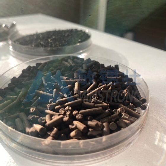
Ozon parçalanma katalizatoru
1. Formation Mechanism of Carbon Fouling and Characteristics of Printing Exhaust
1.1 Sources of Carbon Fouling
During printing and UV curing, substances such as ink, photoinitiator fragments, acrylate monomers, and oil mists enter the ozone catalyst bed along with the exhaust air. Exhaust temperatures from UV curing ovens typically range from 40°C to 60°C. The waste gas contains significant quantities of photoinitiator decomposition products and unreacted acrylate monomers. This organic matter condenses into viscous, oily liquid droplets. These substances adsorb onto the catalyst surface and undergo polycondensation, eventually carbonizing to form a carbon deposit layer. This layer covers active sites and blocks pore channels, hindering the diffusion of ozone molecules into the catalyst’s interior.
1.2 Factors Influencing Carbon Fouling
Several factors influence the rate of carbon fouling formation. Higher concentrations of VOCs and oil mists in the exhaust accelerate fouling. Catalysts with a higher proportion of micropores are more susceptible to blockage by organic matter. Additionally, excessively low bed temperatures lead to incomplete oxidation of organic compounds, increasing the likelihood of deposition.
1.3 Pilot-Scale Data on Carbon Fouling
According to published pilot-scale data, sonra 800 hours of continuous operation in a UV printing workshop, the pressure drop across the catalyst bed rose by approximately 40%. Ozone removal efficiency dropped from 99% to 84%. Catalyst samples appeared black, and the particles showed a weight increase of about 8%. These data reflect the gradual accumulation of carbon deposits. This indicates that this is not a sudden failure but a progressive process that operators can anticipate through monitoring.
2. Diagnostic Methods for Carbon Clogging
2.1 Monitoring Pressure Drop Changes
Assessing carbon deposition requires the comprehensive evaluation of multiple operational indicators rather than reliance on a single parameter. Changes in the catalyst bed pressure drop serve as the most direct signal. Under constant flow conditions, a slow, linear increase in pressure drop indicates normal aging. Lakin, an accelerated rise strongly suggests clogging caused by carbon deposits or dust. Typically, an increase in pressure drop exceeding 30% warrants an investigation into carbon deposition.
2.2 Analyzing Outlet Ozone Concentration
Trends in outlet ozone concentration also offer diagnostic value. Efficiency degradation caused by carbon deposition is usually progressive. The outlet ozone concentration rises slowly over weeks or months, coinciding with the increase in pressure drop. This contrasts sharply with sulfur poisoning, which causes a rapid decline in activity with minimal change in pressure drop.
2.3 Sampling and Analytical Methods
Sampling and analysis serve as the definitive method for confirming carbon deposition. Technicians collect catalyst samples from various locations within the reactor. They observe color changes (carbon-fouled catalysts turn black), measure particle weight gain, and assess the loss of specific surface area via BET analysis. A loss of specific surface area exceeding 30%–40% of the initial value generally indicates severe pore clogging. Additionally, shifts in the reaction temperature window can serve as a supplementary indicator. As carbon deposition reduces the number of active sites, the operating temperature required to achieve a specific ozone conversion rate gradually rises.
3. Operational Conditions and Limits of Thermal Regeneration
3.1 Thermal Calcination Procedures
Thermal calcination is the most common method for regenerating catalysts fouled by carbon deposits. Operators place the deactivated catalyst in a calcination furnace and expose it to airflow at 300–400°C. This oxidizes the carbon deposits into CO₂ for removal. Typical operating conditions include a heating rate of 2–5°C/min to prevent catalyst sintering caused by localized overheating. This is followed by a holding period of 2–4 hours at 350°C. The exact duration depends on the amount of carbon deposition and the catalyst’s thermal stability. According to regeneration procedures documented in public literature, the catalyst is first dried at 100–110°C for 2–3 hours to remove moisture, then calcined at 250°C for 3 saat, and finally calcined at 450°C for 3 saat. The catalyst’s weight decreases by approximately 9% after regeneration, indicating effective removal of carbon deposits.
3.2 Regeneration Performance and Limits
Regarding regeneration performance, activity can typically be restored to over 90% of its initial value following heat treatment. Lakin, operators must recognize limits on the number of regeneration cycles. Repeated high-temperature calcination causes a gradual decline in specific surface area and potential sintering of active components. Consequently, the catalyst usually reaches the end of its service life after 3–5 regeneration cycles, rendering further regeneration unviable.
3.3 Chemical Cleaning Restrictions
Operators should not use chemical cleaning methods for ozone decomposition catalysts. Acidic or alkaline solutions may damage the structure of active components (such as manganese- or copper-based materials) and corrode alumina or molecular sieve supports, resulting in irreversible damage.
4. Key Control Parameters and Safety Considerations for Regeneration
4.1 Managing Heating Rates
The primary control parameter during regeneration is the heating rate. Carbon oxidation is an exothermic reaction. An excessively rapid heating rate can cause localized temperature spikes that may exceed the catalyst’s thermal tolerance limit and lead to sintering. Maintaining a heating rate of 2–5°C/min, combined with appropriate holding periods within the 200–300°C range, facilitates uniform heat distribution.
4.2 Determining Holding Temperatures
Operators must determine holding temperatures and durations based on the catalyst’s thermal stability. The upper temperature limit is typically 400–500°C for manganese-based catalysts and slightly higher for copper-based catalysts. While higher calcination temperatures accelerate carbon removal, they also hasten the sintering of active components, thereby shortening the catalyst’s effective service life post-regeneration.
4.3 Safety and Off-Gas Treatment
Off-gases released during the process contain VOC oxidation products and CO. Therefore, operators must route these gases to an exhaust treatment system rather than discharging them directly. Upon completion of regeneration, the catalyst’s ozone conversion rate and bed pressure drop should be re-tested under standard operating conditions. Operators should compare these results with data from fresh catalyst samples to verify whether the regeneration performance meets expectations. If the activity recovery rate falls below 80%, the necessity of replacing the catalyst should be evaluated.
5. Carbon Deposition Prevention: Upstream Pre-treatment and Operational Management
5.1 Upstream Mechanical Filtration
Reducing the entry of organic matter into the catalyst bed at the source is more cost-effective than post-process regeneration. Installing multi-stage mechanical oil-removal filters upstream of the ozone catalyst is an effective measure. The first stage utilizes a wire mesh filter to capture large oil droplets. The second stage employs a composite glass fiber filter to remove sub-micron oil mist particles. This phase removes the vast majority of liquid oily substances. According to published operational data, a printing waste gas treatment project that adopted a combined process of mechanical filtration and high-voltage electrostatic precipitation saw a significant reduction in oil mist content in the exhaust gas entering the ozone catalyst. This notably extended the catalyst maintenance interval.
5.2 Catalyst Selection and Operational Management
Catalyst selection also influences the tendency for carbon deposition. Preference should be given to catalysts with large pore sizes and carbon-resistant formulations. For honeycomb catalysts, a balance between cell density and pressure drop must be maintained. While high cell density increases contact area, it also makes the catalyst more susceptible to clogging by particulate matter.
Regarding operational management, facilities should establish a system for regularly recording pressure drop and outlet ozone concentration. Operators should initiate an inspection whenever the pressure drop rises by 20%. A 10%–15% margin in catalyst loading capacity should be reserved during the system design phase. This allows for the addition of fresh catalyst to maintain treatment efficiency when carbon deposition causes performance to decline, thereby avoiding production interruptions associated with immediate shutdowns for regeneration. For UV printing workshops with high oil mist concentrations, an activated carbon adsorption unit may be installed upstream of the ozone catalyst as a protective layer to further reduce the organic load entering the catalyst.
Nəticə
In summary, the issue of carbon deposition on ozone catalysts in printing and UV curing workshops is characterized by diagnosability and regenerability. A systematic approach to extending catalyst service life and reducing operational costs involves several key steps. First, use pressure drop monitoring as the primary early-warning method. Second, employ sampling and analysis to identify the type of carbon deposition and rule out other causes of deactivation. Third, restore activity through thermal treatment (calcination) at 300–400°C once carbon deposition is confirmed. Finally, strengthen upstream oil mist pre-treatment and optimize catalyst selection during the design phase.
müəllif:Qloriya
tarix:2026-09-15
WeChat
WeChat ilə QR kodunu skan edin